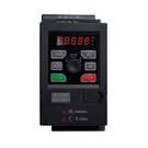
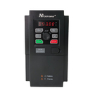
GT20 high performance universal frequency inverter
Performance feature
1.Excellent current control capability,Ensure that the inverter doesn’t trip during the process of fast acceleration.
2.The overexcitation function is automatically added in the deceleration process,deceleration time is shorter.
3.Strong over modulation capability,the output voltage is higher at the same input voltage.
4.Strong overload suppression capability,Ensure that the inverter does not stop due to overload fault at the maximum outpu.ting and dyeing, packaging, printing, pharmaceutical, food, reflow and production line etc.
Function Features
1.Built-in industry-specific macro parameters,Support one-click setting of industry parameters
2.Support external keyboard (LED, LCD keyboard)
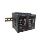
3.Side by side installation, guide rail installation
4.Support keyboard parameter copy
Application
GT20 is a small size smart inverter product, It can be widely used in woodworking carving, glass edge grinding, food filling, medicine centrifuge, automatic production line, electronic equipment, logistics equipment and small automated mechanical equipment etc.
| Category | Terminal Label | Name | Terminal function description | Specification |
| Communication | 485+ | RS485 communication interface |
RS485 differential signal positive terminal | For standard RS485 communicationinterface, please use twisted pair orshielded wire. |
| 485- | RS485 differential signal negative terminal | |||
| Multifunctional output terminal | DO1 | Open collector output terminal | lt can be programmed and defined as switchoutput terminal with multiple functions, seeterminal function parameter F6.11 for details,output terminal function introduction (commonport CME) | Optocoupler isolated output;Working voltage range 9-30V;Maximum output current: 50mA |
| Multifunctiona loutput terminal | DO2 | Open collector output terminal | lt can be programmed and defined as switchoutput terminal with multiple functions, seeterminal function parameter F6.12 for details,output terminal function introduction (commonport CME) | Optocoupler isolated output;Working voltage range 9-30V;Maximum output current: 50mA;Maximum output frequency: 50KHZ; |
| Analog lnput | AI1 | Analog input Al1 | Al1 terminal receiving analog current, andvoltage input (selected and switched throughjump cap) |
lnput voltage range: 0~10V (inputimpedance: 102KQ) Resolution: 1/1000 lnput current range: 0~20mA (inputimpedance: 255Q) Resolution: 1/1000 |
| AI2 | Analog input AI2 | Receives analog voltage input | ||
| Analo Output | AO1 | Analog output | Provides analog voltage output,which can correspond to 12 physical quantities (see F5.25for details) |
Voltage output range: 0~10V |
| AO2 | Analog output | Provides analog voltage output,and currentoutput (AO2 terminal can be realized by jumpcap) can correspond to 12 physical quantities(see F5.26 for details) |
Voltage output range: 0~10V Current output range: 0~20mA |
|
| Multifunctional input terminal | DI1 | Multifunctional input terminal 1 |
lt can be programmed and defined as switchinput terminal with multiple functions, see Chapter Vl terminal function parameters (switchinput and output) input terminal function (See F6.0O-6.04 for details) |
The forward and reverse functions canbe configured for the terminal; Dl5 canbe used as a high-speed pulse inputterminal, and the upper limit of theinput frequency is 50KHZ. |
| DI2 | Multifunctional input terminal 2 | |||
| DI3 | Multifunctional input terminal 3 | |||
| DI4 | Multifunctional input terminal 4 | |||
| DI5 | Multifunctional input terminal 5 | |||
| Power supply | 10V | +10V power supply | Provides +10V power supply for external | Maximum output current: 20mA. |
| +24V | +24V power supply | Digital signal power supply | Maximum output current: 100mA. | |
| GND | Power supply common port | Power reference ground(including +10V and +24V) | lt is the only ground system on the control board. | |
| PLC | Multifunctional input common port | Common port of DI1-DI5 | Shot-circuited to 24V when leaving thefactory. | |
| CME | Digital output common port | Common port of multifunctional DO1 and DO2. | Short-circuited to GND when leavingthe factory. | |
| Relay output terminal |
TA TB TC
|
Programmable relay output | Usually,TA-TB is normally off, and TA-TC isnormally on; during operating,TA-TB isnormally on, and TA-TC is normally off. |
Electric shock rating: NO:5A250VAC; NC: 3A 250VAC. |


